


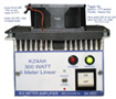
Because I broke several PA transistor sets, I decided to upgrade the PA board. It now uses a BLF188XR FET. With this, I could make a KW when driving it from my Elecraft K2. Since my output filters max-out at about 300 watts, I added an attenuator on the input. Not quite so easy to drive over 300 - 400 watts out now. I hope at this power level it is bullet proof!
Please email me if you have any problems with this page.
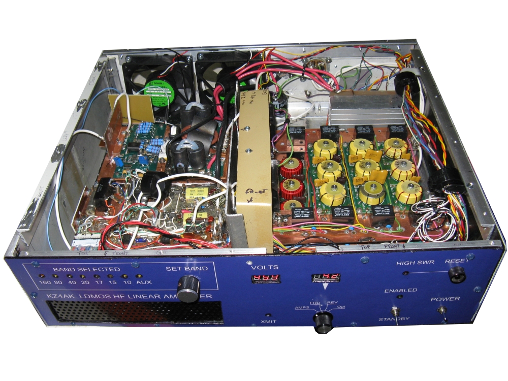 Here is the latest version of my earlier LDMOS HF linear amp.
Click thumbnail for inside view.
Here is the latest version of my earlier LDMOS HF linear amp.
Click thumbnail for inside view.
Zapped the LDMOS in the previous version (Ouch! $). Servicing it was difficult (no easy access) so increased the case size. This gave me space to add a protection circuit also.
The PA board is a LDMOS pallet amp (Russian). About everything else is scratch built. When driven by my Elecraft K2, the PA has enough gain to exceed 600 watts out. I added a 6db input filter to avoid overdrive. The LP filter capacitors have been upgraded to 1 KV.
Most schematics are in a ZIP file (8.2 MB). Click 
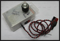
Not included in the ZIP file is a later addition of a heat sink temperature readout that also controls the cooling fans (ON @ 50 degrees C). Click here for schematic: 
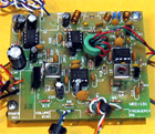
 My uBITX project.
Sold as a board by hfsignals.com, the uBITX v4 requires a few mods for proper operation.
I also added a RF preamp, AGC/Attenuator, audio amps, RF power meter, etc.
Still need to figure out why I get 2 to 3 watts, not 10+ output.
A lot of build information is in a ZIP file (3.8 Meg file). Click thumbnail image to download the ZIP file.
Click the circuit board for a circuit board layout of the RX amplifier - attenuator I added to the uBITX.
 Find your power line RFI
Sold as a kit, the Vectronics AM aircraft receiver is great for sniffing-out power line RFI.
Here is my build... Click thumbnail image to load more information, PDF.
 Here is a very simple, yet high performance FIELD STRENGTH METER.
Scroll down below the Log Power Meter...
Range is about -60 dBm to +10 dBm - to 500 MHz. Includes pictures and circuit.
NOTE: There is an error in the schematic PDF.
Here is the corrected schematic...

 75 Meter SSB TRANSCEIVER, 10 Watts Output.
Download documentation (all there is) for the 75M TRANSCIEVER.
...Images of some of the circuits in a zip file.
...Documentation very incomplete!
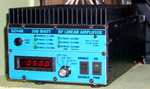
 6 METER LINEAR AMPLIFIER using an MRF141G (AR313 design)
Now Deceased!
Download all ZIP of all documentation and pictures for the above 6M amp. NOTE it is a 21 MB file.
After a year of good service, blew the MRF141G. After blowing a total of 3 devices, I think I know what went wrong. Something happened to the output filter that presented a very high SWR to the PA. At the same time, my Bird wattmeter slug died which resulted in showing much less output than what was really happening. This resulted in me overdriving the amp into a high SWR. Now replacing the homebrew amp with a Beko HLV-950. Now I need to avoid smoking my yagi antenna !!
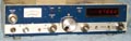
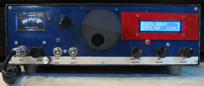
 20M SSB TRANSCEIVER, 10 Watts Ouput. Typically used to drive my homebrew 6M transverter.
Download documentation (all there is) for the 20M Rig.
...Images of some of the circuits in a zip file.
...Documentation somewhat incomplete. Uses out of production Plessy ICs in SSB generator.
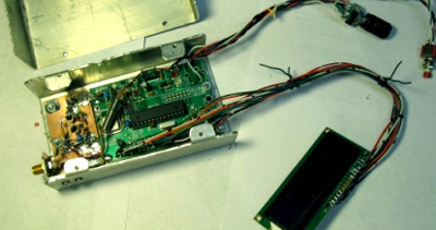
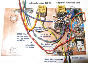
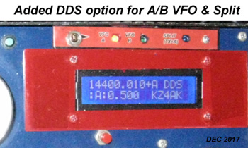
The 20M rig has been updated using a DDS for the VFO (kit from N3ZI with homebrew buffer amp) and have added a PC/Sound Card interface so I can use FT8, MSK, etc.
Here are pictures of the front after adding the DDS, a picture of the DDS, and the PC interface that I installed. The red bezel covers the larger hole used for the old display. Sorry, all I had was red paint at the time! The last image is after adding the DDS VFO control mod.
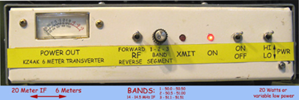
 SIX METER LINEAR TRANSVERTER. 1 Wt. at 20 meters -to- 20 Wt. at 6 m.
The 6 Meter Transverter has been updated to include a variable attenuator. (front panel trimpot). Now I can run the BEKO 6 Meter amplifier from less than 100 watts to a KW output, or barefoot, from <1 watt to 20 watts.
Here is the revised front panel...
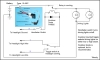
 A sample schematic from the ZIPed package below.
Download all info (ZIP file) for the Six Meter Transverter. (20 MB)
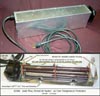
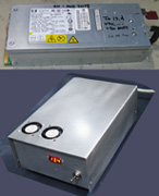 13.4 VDC, >50 Amp power supply. High power on a budget.
Connection information for a HP DPS-800GB "server" P.S. and how I implemented one.
Low cost for 13 volts at 50 amps!
The supplies can be found online in the price range of $10 (like ebay).
Click thumbnail image to load more information, PDF.
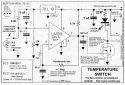
Click schematic for info on the fan controller I added. A thermistor controls the enclosure exhaust fan power./
 Millen Grid Dip Meter - Click for FULL FACTORY MANUAL - (10 MB PDF)
Click to download the brochure...
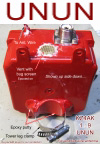 Here is the high power 1 : 9 UNUN that I use for my end fed wire antennas.
Enough details to build one.
Here is the high power 1 : 9 UNUN that I use for my end fed wire antennas.
Enough details to build one.
This was designed to clamp on a Rohn 24 tower leg, but should work well against many grounds.
It is recommended for the coax leaving the UNUN to have a common mode choke - Either with a number of turns of the feed coax or a string of ferrite beads.
Click image to view PDF.
 Download schematic for my MOTORCYCLE DRIVING LIGHT CONTROL. Lights are enabled either on high beam or low (toggle switch selectable) with an independent on/off switch. Use a 12 volt relay rated to handle the light current (amps). The Hi/Lo select toggle is a booted minature mounted in the headlight cowling.
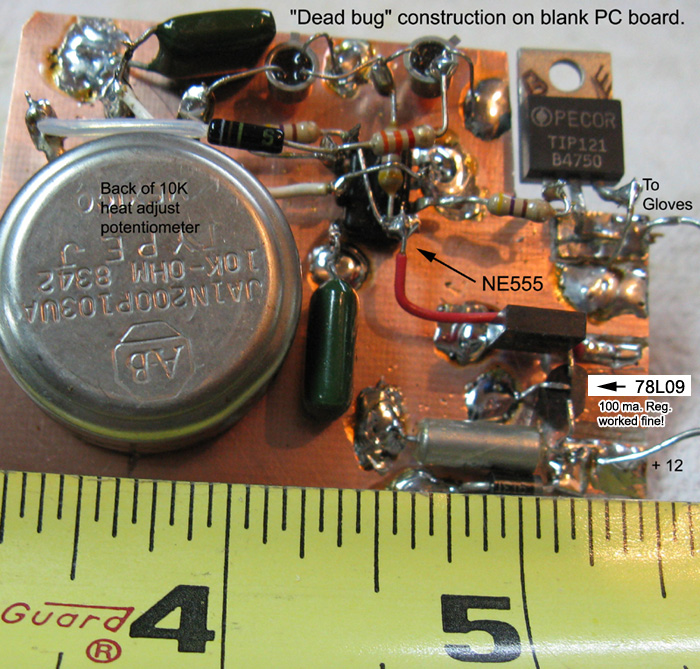
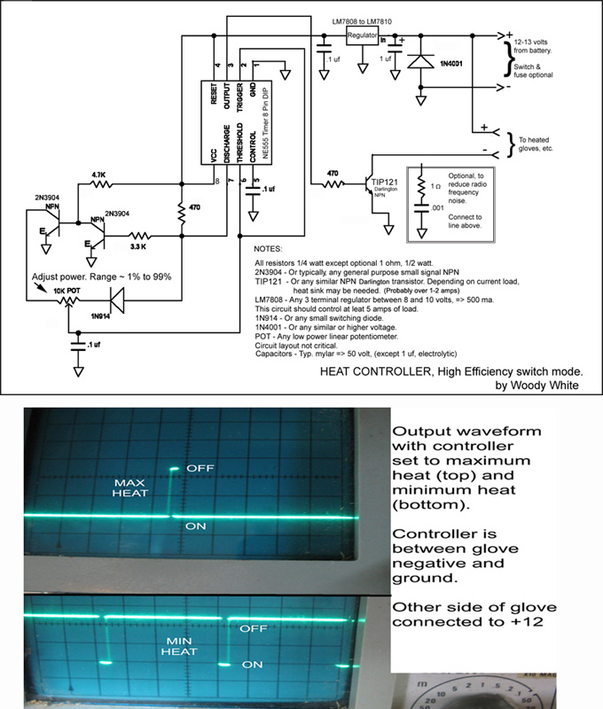
 Click image to download schematic diagram for my HEATED MOTORCYCLE GLOVE CONTROLLER. Highly effencient switch mode.
Adjusts glove power from about 1% to 99%. Tested up to 4 amps. Use browser BACK button to return.
CLICK HERE for picture of assembly
CLICK HERE for picture the schematic and output waveforms
 Pictures of my Mark II MARINE ENGINE COMPARTMENT HEATER. The heater controller schematic is from my Mark I unit. The Mark II controller is similar, but without the 120 volt auto transformer. A gell cell battery, smart charger, and 7 watt pulsating siren (tripped by a on-boat motion sensor) are included in the controller. It drives an external horn speaker.
After getting to this section, USE PULL-DOWN AT BOTTOM FOR MORE INFO
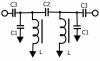
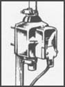
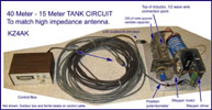 Here is a picture of a "tank circuit" antenna match that remotely tunes from 40 through 15 meters. It matches 1/2 wave end fed wires.
 This PDF file describes my modification of an Elecraft K2 for PSK31, RTTY, Etc.
 This ZIPed file is a simple calculator for HF bandpass filter design.
Requires vbrun300.dll ** NOTE ** : May not run on newer Windows systems.
 E-Z Design of a 3-TERMINAL VOLTAGE REGULLATOR.
FYI : The links in the PDF are out of date.
 HIGH CURRENT 13 VOLT LINEAR POWER SUPPLY. Linear, 13.6 Volts, 80 Amps. Cont.
Retired in May 2018 after it failed. 45 years service, not bad!
Download schematics for the above power supply. Zipped package of bitmapped .tif files.
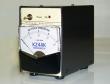
 SOLID STATE HF LINEAR, 160M to 10 M, 10 Wt. input, 250 Wt. Output.
This was my first "big" SS HF linear amplifier. Appearing next is my second linear.
Mods: February 2003
Replaced PA transistors (4) with Matched Quad from RF Parts Co. -
#SRF3800, added attenuator to PA board input - Inline w/coax., Added heat sink cooling fan. -Energized when amp in "OPerate" mode.,
Adjusted Power out cal pot and ALC cal pot...
Now: >300 watts out with less drive!
Download schematics for the above amplifier.
...Includes nice LP Filters, bias, etc. Based on Ham Radio Mag. articles of yesteryear.
Zipped package of .jpg files.
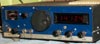
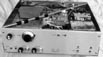
 SOLID STATE HF LINEAR, 160M to 10 M, 6 Wt. input, 250 Wt. Output.
This project has been disassembled
and the parts used to fabricate my latest version, at the top of this page.
This is my second "big" SS HF linear amplifier. Includes 17M WARC band, my favorite.
It uses the AN-758 PA board from Connumications Concepts. DC power is 45-50 VDC
Click "Download" for a 1.4MB PDF file with construction details. Scroll down
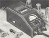
 DIRECT READING SWR/POWER METER.
Download the 1973 article. Zipped image files.
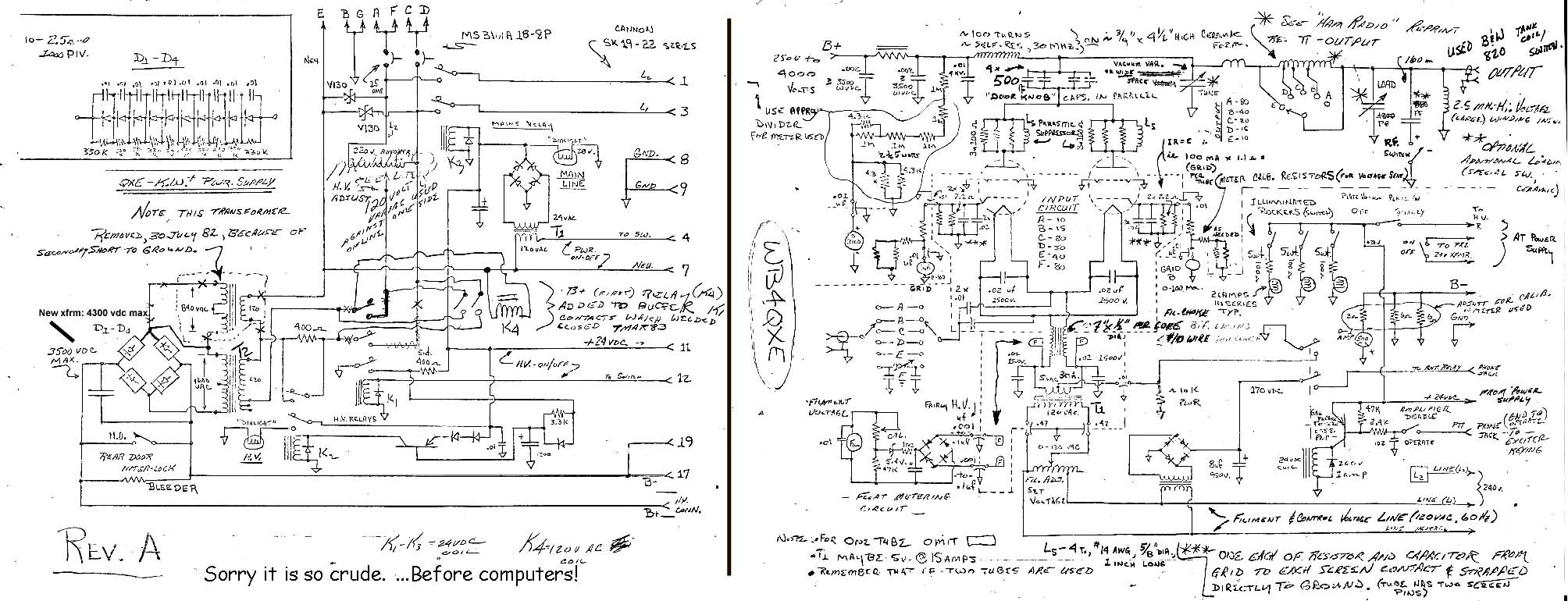
 HF LINEAR AMPLIFIER, using a pair of cathode driven 4-400 Tubes.
Click Here for a truly junky schematic for the 4-400s. File: 282K
CAUTION, An error was brought to my attention. The B+ should pass through the choke and be connected to the lower side of the doorknob blocking capacitors. NOT STRAIGHT THROUGH !!
Thanks, Terry!
 ATV REPEATER - NTSC, 70 cm input, 33 cm output, AM. Picture Only
 ATV TRANSMITTER (MK-III) 15 Watts peak output (NTSC) on 70 cm.
Download schematics for the MK-III ATV transmitter above. Hetrodynes (mixes) to 70cm from Ch3/4 "modulator".
 Another implementation of the MK-III design. Includes video switch for cross band RPT. Picture Only
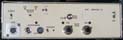 NTSC ATV - Includes: 10 Wt. 70 cm Tx and 70 cm & 33 cm Rx downconverters. Picture Only
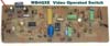 Picture of a VIDEO OPERATED SWITCH. To downoad circuit, click next link...
 Video Operated Switch - Turn on your ATV monitor / sound alarm when signal present.
 ALLIANCE U-100 ROTATOR SERVICE MANUAL (4 jpg images - zipped)
Click thumbnail to download.
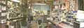 The Ham Shack Site of "KZ4AK (WB4QXE) Homebrew Lab"